 |
FITTING TUBULAR WISHBONES
Having
now put the five-speed gearbox conversion on the
backburner for the
time being, I now wanted a winter project for the
good old Locust.
Something to get me out into the garage on a cold
winter night and up
to my armpits in engine oil a grease.

Casting my mind back to July 2003, on a "run"
out with the Club, into
the Heart of the Kent countryside to visit the
"Darling Buds of May"
car show,prompted a new project that would fit
the bill.
After
leaving the above car show, we had cause to visit
a lovely county Pub (
as you do ) and have a beer. ( only one, drinking
& driving ) Yours
truly got stuck on the exit out of the car park
with the front cross
member scraping on kerbstones between the car park
and the road. After
backing off a couple of times, I managed to get
the Locust back on to
the main road. Now I have always had a very low
front cross member. (I
will wait for the laughter to subside) The front
suspension on my
chassis, which is the White Rose vintage from
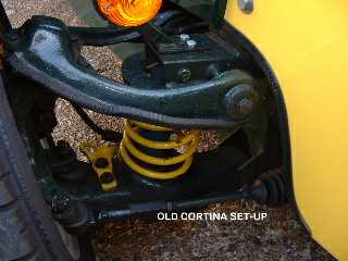
around 1996, has the
Cortina set-up. As the car has been on the road
for some 3-4 years, the
front suspension has "settled", leaving the Front
cross member about 2"
clearance off the ground. The only way to increase
the ride height was
to put spacers under the coil springs or longer
springs in order to
push the front up, but this is a hit and miss
affaire.
The other
problem with the Cortina set-up is you cannot
alter the caster or
camber angles which leads me on to another
annoying problem. From day
one, whenever the steering wheel was turned,
either left or right, the
steering wheel would not self-centre. I could take
my hands off the
steering wheel and the car would continue in the
same direction.. The
Locust, I hasten to add, in this situation, was
not dangerous. It was
more like very neutral oversteer. which talking
with other Club
members, also seem to have a similar problem. The
cause is, lack of
caster angle, which on my car is actually 0 degs,
when it should be
about 5 deg plus. Anyway on with the winter
project.
To remain within the limits of travel of the top
& bottom ball
joints, be aware that there are two different
types of Locust chassis
and the distance between the top & bottom
wishbone pivot points
will vary between the two types. The chassis which
White Rose
manufactured has the suspension "towers"
fabricated from sheet steel.
Measure the distance between top and bottom
wishbone pivot points and
you should have a measurement of 216mm. Mount your
top wishbone as Fig
1.
 |
|
 |
Pre
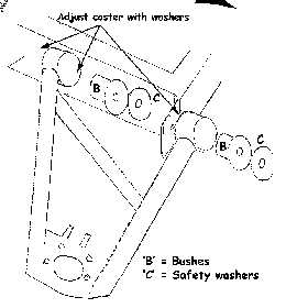
White Rose chassis has the suspension "towers"
made from box section,
like the chassis rails. Measurement for this
should be 260mm and mount
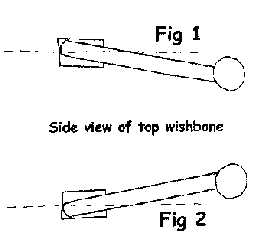
the top wishbone as in Fig 2.
Jack up car, take off wheels, brake calliper, and
all the old Cortina
wishbone components.
New Wishbones arrived, complete with
brackets and after stripping
off the paint, I took them off to be Power Coated
in Black.
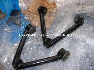
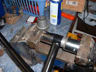
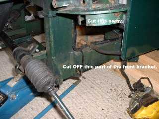
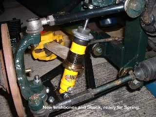
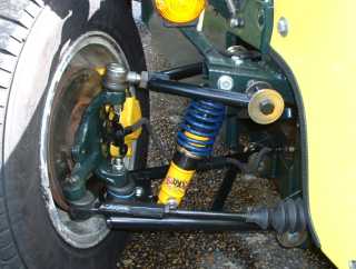
8
Ford new bushes from a Cortina Part No. 6009975
were pressed into the
newly painted top & bottom wishbones, using a
large vice and large
32mm sockets.
The
large angled flange bracket which held the tie-rod
was cut off using an
Angle grinder, as this was not required and so was
the rear bracket
from the old front tie rod bracket.
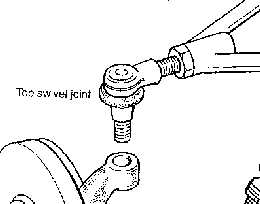
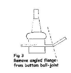
Two
Top Ball joints from Ford Transit van & Two
Lower Ball joints from
Ford Cortina are required, with the angle flange
cut off the lower ball
joints, which are then bolted from the underside
of the bottom
wishbone.
Now,
being a complete dork at welding, I called upon
the services of a
mobile welder to fix the new Front and rear
Brackets, loosely
assembling them into position using new bolts.

After
a couple of coats of paint on the new brackets to
was time to measured
the length required from the top and bottom
mounting points in order to
establish the "stroke" of the shock when opened
and closed.

1.
Chock up the front of the chassis to achieve the
required ground
clearance, using 4" x 2" wood complete with hubs,
steering rack and
wheels. I was aiming for 4" ground clearance under
the front cross
member.
2. Keep the wishbones in the same place by
inserting wood blocks and
then remove road wheels.
3. Measure the distance between the top and bottom
shock absorber
mountings. This will be your mid point as the
shock compresses. Mine
was 29mm. Lift the Hub & wishbone
assembly to
check the point where either track rod ends or
upper & lower ball
joints starts to reach the end of its travel.
Lower the assembly at
least 15mm and again measure the distance between
the mounting points.
This will be the "closed" length of the coil over.
4. Lower the hub & Wishbone assembly back
to its blocks.
5. Remove the blocks from under the wishbone
assembly
and lower the Hub/Wishbones
assembly to the end of there travel where
the ball joints, upper & lower start to bind.
This is now the
"open" length of the coil over.
6. With
these measurements, you should be able to lift the
assembly by about
15mm and measure between the mounting points in
order to find the
correct Shock Absorbers length to buy. You should
find that the
"stroke" of your coil over will let the wheels
move up & down
approx. 3-4" and that I am told is OK for car of
our type. Don't BUY
THE SPRINGS YET. Just get the shocks.
The Shock Absorbers that I went for were the SPAX
G2034 1.9" Adjustable
RSX damper, which comes off of all things, a
Mini!!!!!!! A lovely pair
of Yellow Shocks turn up, and after fitting then
on it was obvious that
they would foul the old support ring on the Shock
tower.Out with the
grinder.
 |
|
 |
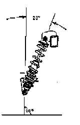
Next
to buy was the 1.9" springs. What is the correct
spring rate when
fitting coil over suspension. There is NO exact
answer to this. It will
depend on several factors. I understand that when
WRV first started
selling the wishbones, they advised the use of 150
lbs springs and
updated to 180 lbs. I went for 150 lbs as the
springs can be stiffened
up using the adjustment spring pan rings.
So before you
rush out and buy
new springs, you will need to work out
the "Effective Spring Rate". This will depend on
what angle your Coil
Over's are mounted at. When I mount my Shock's, I
put mine back into
the original top holes
making the Shocks nearly upright.

My
coils over are mounted at 20 degs, which if I was
aiming for a Spring
poundage of 150 lbs, I had to fit Springs rated @
170 lbs to aim for an
effective spring rate of 150 lbs. Take a look at
the Chart if your
brain has gone into overload.
Spring
Angle |
10 Deg |
15 Deg |
20 Deg |
25 Deg |
30 Deg |
35 Deg |
40 Deg |
45 Deg |
Effective rate |
0.96 |
0.93
|
0.88
|
0.82
|
0.75
|
0.66
|
0.59
|
0.50
|
You
can see from the chart that if your Coil over is
at 45 deg, your 150 lb
string is only 50% effective, in other words it
is only about 75 lbs.
I wanted 150 lbs
effective.>150 divided by 0.88 ( my 20 deg
angle ) equals 170 lbs
spring.
What I wanted next was the spring length.
1. Bolt the Shock and wishbone up, complete with
hubs, steering rack
and wheels yet again.
2. Chock up the front cross member of the
chassis to achieve the
required ground clearance. I was aiming for 4"
3. Wind down the adjustable rings on the shock,
as far as
possible and measure the distance from the rings
to the top mounting
face. Mine was 6". I then order up Two 6"
long x 170 lb springs,
and when they
arrived, it was a simple case of re-assemble on
to the shocks. With the
suspension all assembled and the car now on
level ground it was to
adjust the tracking to approx. 0 deg (I will
take the car into a tyre
centre to get it checked more precisely) and to
adjust the camber
angle. The castor setting was determined by
inserting spacer washers on
the lower bracket which has give about 5 deg + .
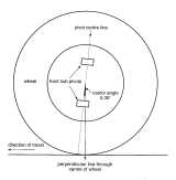
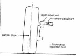
The
ride high under the front cross member was now a
tad under 4" after
winding up the shock absorber spring adjustment
rings to about half way
up the threaded part of the shock. The camber
angle was now set at 0
deg and the "toe-in" at 0.05 deg by using a tape
measure,( this was
checked a couple of weeks later by a Tyre company
to be actually 9 deg
of "toe-out". So much for using a tape measure.
The camber angle was
spot-on.) and after checking all the nuts and
bolts have been tightened
up, new split pins installed through the Castle
nuts.
 |
|
 |
So
out for a test run, and as it was in middle of
February ( and YES the
car is Taxed, MOT ed and Insured) so it was only
a quick trip round the
block to see how it would respond. A quick test
on the brakes, and the
car pulled up in a straight line. So far so
good. Up to the T junction
and a left turn, and immediately I could feel
the steering wheel trying
to straighten up. Not strongly, but just like a
normal car should be.
Next test was a few bumps to test the
suspension. It felt a little
stiffer than with the old set-up but apart from
that, all felt good.
The best part, was driving the car back into the
garage, as a 1" high
lip in the concrete had always "grounded" the
car halfway down the
chassis. The only way to get the Locust in, was
to lay down scaffold
planks and drive into the garage on them. No
problems with the new
set-up. Was it all worth it in money terms.
Well, here's the costing
Top and bottom
Whishbones |
|
£110 |
Power Coating |
|
£25 |
Mobile Welder |
|
£25 |
Nuts, Bolts, & Washers |
|
£15 |
Bushes |
|
£32 |
Top Ball joints |
|
£15 |
Lower Ball joints |
|
£24 |
Spax AVO adjustable shocks |
|
£170 |
Springs |
|
£65 |
Spax AVO adjustable shocks |
|
£170 |
Total |
|
£481 |

A
lot of money, but the car handles better, look's
better, the suspension
is more "tweakable", steering wheel self
centres, goes in garage and
better still, not likely to "lose" the sump when
going in Pub car
parks!!!!!!!!!!
Happy
Locusting............
Chris Laycock.
Many thanks to Phil Manship
for his
very useful information, both written and verbal
on the above project.
|
 |